


Creating an enterprise architecture diagram is a significant step in visualizing complex business and IT landscapes. ArchiMate provides a structured framework for this, but navigating its rules can be challenging for newcomers. When building your initial model, you may encounter issues with relationship validity, layer alignment, or visual clutter. This guide addresses common stumbling blocks and offers practical strategies to ensure your diagrams communicate effectively.
Clear modeling is not just about aesthetics; it is about logical integrity. A diagram that looks good but breaks the language rules can lead to misinterpretation during critical planning phases. By focusing on consistency and troubleshooting early, you establish a foundation for a robust architecture repository. Let’s explore the core areas where beginners typically face difficulties and how to resolve them.
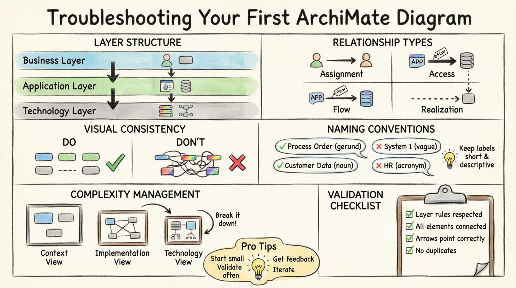
🧩 Understanding the Layer Structure
One of the most frequent sources of confusion involves the three core layers of the ArchiMate framework: Business, Application, and Technology. Each layer serves a distinct purpose, and mixing them incorrectly can invalidate relationships.
Business Layer
This layer focuses on the organization’s goals, processes, roles, and artifacts. It answers the “what” of the organization. If you are modeling a process like “Order Processing,” it belongs here.
Application Layer
This layer represents the software systems that support the business. It includes applications, application components, and data objects. This is where you map the “how” the business processes are supported technically.
Technology Layer
This layer details the infrastructure required to run the applications. It includes hardware, networks, and system software. This is the physical foundation.
When troubleshooting, check your layer assignments first. If an Application Component is directly connected to a Business Actor without an intermediate process or function, the relationship might be missing context. Ensure that the flow of information and support respects the boundaries between these layers.
🔗 Validating Relationships and Connections
Relationships define how elements interact. In your first diagram, you might be tempted to connect any two elements that seem related. However, ArchiMate defines specific relationship types with strict directionality and layer constraints.
Common Relationship Errors
- Assignment vs. Access: An Assignment relationship connects a Business Actor to a Business Role. An Access relationship connects an Application Component to a Data Object. Do not confuse these. If an actor uses a role, use Assignment. If a system uses data, use Access.
- Flow vs. Serving: A Flow relationship is used for business objects moving between processes. A Serving relationship connects an Application Component to a Business Process. Mixing these up can obscure the actual support mechanism.
- Triggering vs. Realization: Triggering is typically used between processes to show sequence. Realization shows how a structure (like a component) realizes a behavior (like a process). Ensure you are not using Triggering for structural dependencies.
| Relationship Type | Direction | Common Use Case |
|---|---|---|
| Assignment | Actor to Role | Manager leads Team |
| Access | App to Data | System reads Database |
| Flow | Process to Process | Step A leads to Step B |
| Realization | Structure to Behavior | Component implements Process |
If you find a connection that feels forced, pause and review the definition. Does the source element actually enable or support the target element according to the language specification?
📏 Maintaining Visual Consistency
Clarity is often lost not because of logical errors, but because of visual inconsistency. When a diagram is difficult to scan, stakeholders may miss critical dependencies. Consistency in styling and layout helps the reader focus on the architecture, not the formatting.
Standardizing Shapes and Colors
While some tools allow extensive customization, it is best to adhere to standard conventions. This ensures that anyone reviewing the diagram understands the notation immediately.
- Shapes: Use standard shapes for each element type. For example, a Business Process is typically a rectangle with rounded corners, while a Business Actor is a stick figure. Do not change these arbitrarily.
- Colors: Assign a consistent color palette to layers. For instance, keep all Business elements in blue, Applications in green, and Technology in grey. Avoid using multiple colors for the same element type within a single diagram.
- Line Styles: Use solid lines for flow and assignment. Use dashed lines for realization or dependency. Keep arrowheads consistent.
When troubleshooting a cluttered diagram, check if you have used too many colors or too many different shapes for similar elements. Simplify the visual language to reduce cognitive load.
📝 Naming Conventions and Labels
Labels are the text inside or near the elements. Poor labeling is a common cause of ambiguity. If a reader has to guess what an element represents, the diagram has failed.
Best Practices for Text
- Use Gerunds for Processes: Business processes should be named with verbs ending in -ing (e.g., “Process Order”, “Manage Inventory”). This indicates action.
- Use Nouns for Objects: Business objects, data objects, and applications should be nouns (e.g., “Customer Data”, “Order System”). This indicates a static entity.
- Avoid Acronyms: Unless they are universally understood within your organization, write out full terms. “HR” is better as “Human Resources” for a general audience.
- Keep it Short: Long labels break the visual flow. If an explanation is needed, use the description field, not the label.
When reviewing your diagram, look for labels that are vague. “System 1” tells the reader nothing. “Inventory Management System” provides immediate context.
🔄 Handling Complexity and Scope
One of the biggest challenges in the beginning is trying to put everything on one screen. This leads to spaghetti diagrams where lines cross everywhere, making relationships impossible to trace.
Strategy: Decomposition
If a diagram is too crowded, it is a sign that you need to break it down. ArchiMate supports multiple views and levels of detail.
- Context View: Show the high-level business capabilities and major applications. Do not include technology details here.
- Implementation View: Focus on the specific components and their interactions. This is where you detail the software stack.
- Technology View: Isolate the infrastructure. Map the servers and networks without the business overhead.
Do not force a single diagram to show every detail. Use reference points to indicate where a sub-diagram exists. This keeps the main view clean while preserving the ability to drill down.
🧪 Consistency Checks and Validation
Before finalizing a diagram, perform a systematic check. This helps catch errors that the eye might miss during the design process.
Validation Checklist
- Layer Rules: Verify that no relationships cross layers inappropriately. For example, a Business Actor should not directly access a Technology Server.
- Connectivity: Ensure every element is connected to at least one other element. Orphaned elements usually indicate incomplete modeling.
- Directionality: Check that arrows point in the correct direction. A flow from A to B is different from B to A.
- Redundancy: Look for duplicate elements. If “Order Processing” appears twice, merge them or rename one to reflect a variation.
| Issue | Diagnosis | Fix |
|---|---|---|
| Broken Line | Relationship has no target | Drag the line to the correct element |
| Label Overlap | Text covers another shape | Reposition elements or resize labels |
| Layer Mix | Business connected to Tech directly | Add Application layer intermediate |
| Orphan Node | Element has no connections | Connect to relevant process or system |
🤝 Collaboration and Review
Architecture is rarely a solo effort. Getting feedback from stakeholders helps identify gaps in logic or understanding.
- Peer Review: Have a colleague walk through the diagram. Ask them to explain the flow without your input. If they hesitate, the diagram is unclear.
- Stakeholder Walkthrough: Present the diagram to business owners. Does it accurately reflect their reality? If they say “We do it differently,” update the model.
- Version Control: Keep track of changes. If you modify a relationship, note why. This history helps in future troubleshooting.
🛠️ Common Troubleshooting Scenarios
Here are specific scenarios you might face and how to approach them.
Scenario 1: Too Many Crossings
Symptom: Lines cross each other chaotically.
Resolution: Reorganize the layout. Group related elements together. Use sub-diagrams to isolate complex clusters. Consider using a different layout algorithm if your tool supports it.
Scenario 2: Unclear Dependencies
Symptom: You cannot tell which process drives which application.
Resolution: Add explicit “Serving” relationships. Ensure the arrow points from the Application to the Process it supports. Add labels to clarify the nature of the dependency.
Scenario 3: Confusing Data Flow
Symptom: It is hard to see where data originates.
Resolution: Use “Flow” relationships for data objects. Ensure the data object is attached to the process that creates it. Use “Access” for consumption.
🚀 Moving Forward
Building ArchiMate diagrams is an iterative process. Your first attempt will not be perfect, and that is expected. The goal is to create a model that is understandable and maintainable. By focusing on layer integrity, relationship correctness, and visual consistency, you can troubleshoot issues before they become entrenched in the model.
Remember that the value of the diagram lies in its ability to communicate. If the stakeholders can read it and make decisions, the modeling effort has succeeded. Keep refining, keep validating, and keep the structure clear.
With practice, the rules will become second nature. You will find that the framework supports your thinking rather than restricting it. Start small, validate often, and build complexity gradually.

