Understanding UML Use Case Modeling: The Online Shopping System Architecture
In the realm of software engineering and system analysis, the Use Case Diagram serves as the bridge between high-level business requirements and detailed technical design. It is the primary tool used to visualize the functional requirements of a system from the perspective of the users (actors) who interact with it.
Based on the visual output generated by the Visual Paradigm AI Chatbot, we will deconstruct the architecture of an Online Shopping System. This tutorial will guide you through identifying the actors, defining the use cases, and understanding the complex relationships—such as extensions—that drive the system’s logic.
1. Identifying the Actors (The Users)
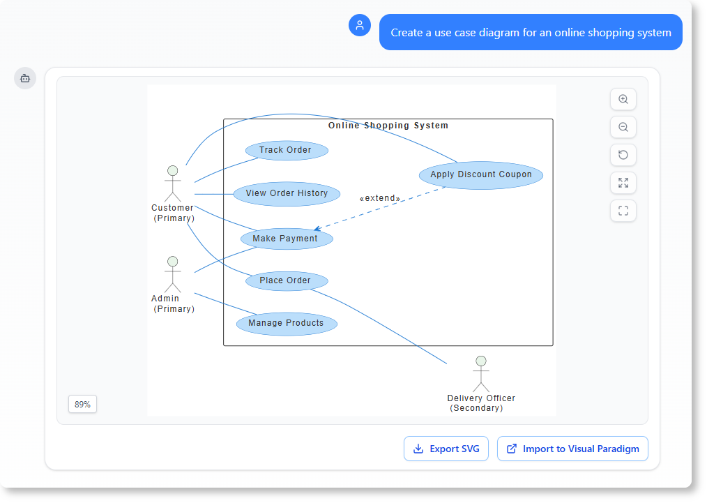
Actors represent the external entities that interact with the system. In this specific architecture, the AI has identified three distinct roles, each with a specific relationship to the system’s boundaries:
- Customer (Primary): The main user of the system. This actor initiates the core business processes, such as shopping and paying. The label “(Primary)” indicates that this is the central stakeholder for the majority of the system’s functionality.
- Admin (Primary): A system administrator or manager responsible for backend operations. They do not “shop” but rather maintain the system’s integrity by managing products and data.
- Delivery Officer (Secondary): An external role that interacts with the system to fulfill the final stage of the business process. The “(Secondary)” tag suggests they are involved in specific sub-processes rather than the entire workflow.
2. Defining the Use Cases (The Actions)
The ovals inside the system boundary represent Use Cases. These are specific goals or actions that an actor can perform. Let’s break down the five core functions identified in the diagram:
- Track Order: Allows the Customer to monitor the status of their shipment.
- View Order History: Provides the Customer with a log of past transactions.
- Make Payment: The critical transactional step where the customer completes the purchase.
- Place Order: The finalization of the shopping cart into a system record.
- Manage Products: The administrative function for adding, editing, or deleting inventory items.
3. Advanced Relationship Modeling: The «extend» Relationship
The most sophisticated concept in this diagram is the relationship between Make Payment and Apply Discount Coupon.
Notice the dashed arrow pointing from “Apply Discount Coupon” to “Make Payment” labeled with «extend». In UML terminology, an extend relationship implies that the extending use case (Applying Coupon) adds behavior to the base use case (Making Payment) only under specific conditions.
How this works logically:
- The primary flow is the Customer performs Make Payment.
- However, if a specific condition is met (e.g., the customer has a valid coupon), the system extends this flow.
- The Apply Discount Coupon use case is executed.
- Once the coupon is applied, the system returns to the Make Payment flow to complete the transaction with the discounted price.
4. System Context and Boundaries
The large rectangle in the center represents the System Boundary for the “Online Shopping System.” Everything inside this box is part of the software being built. Everything outside (the stick figures) is external to the software. The lines connecting the actors to the ovals are called Associations, representing the communication channels between the user and the system.
Summary of the Workflow
This diagram provides a complete “map” of the system’s capabilities. A developer could take this high-level model and immediately begin writing the code for the core logic, while a project manager could use it to verify that all customer needs (like tracking and discounts) have been accounted for.