Mastering UML Use Case AI: From Concept to Code with Visual Paradigm
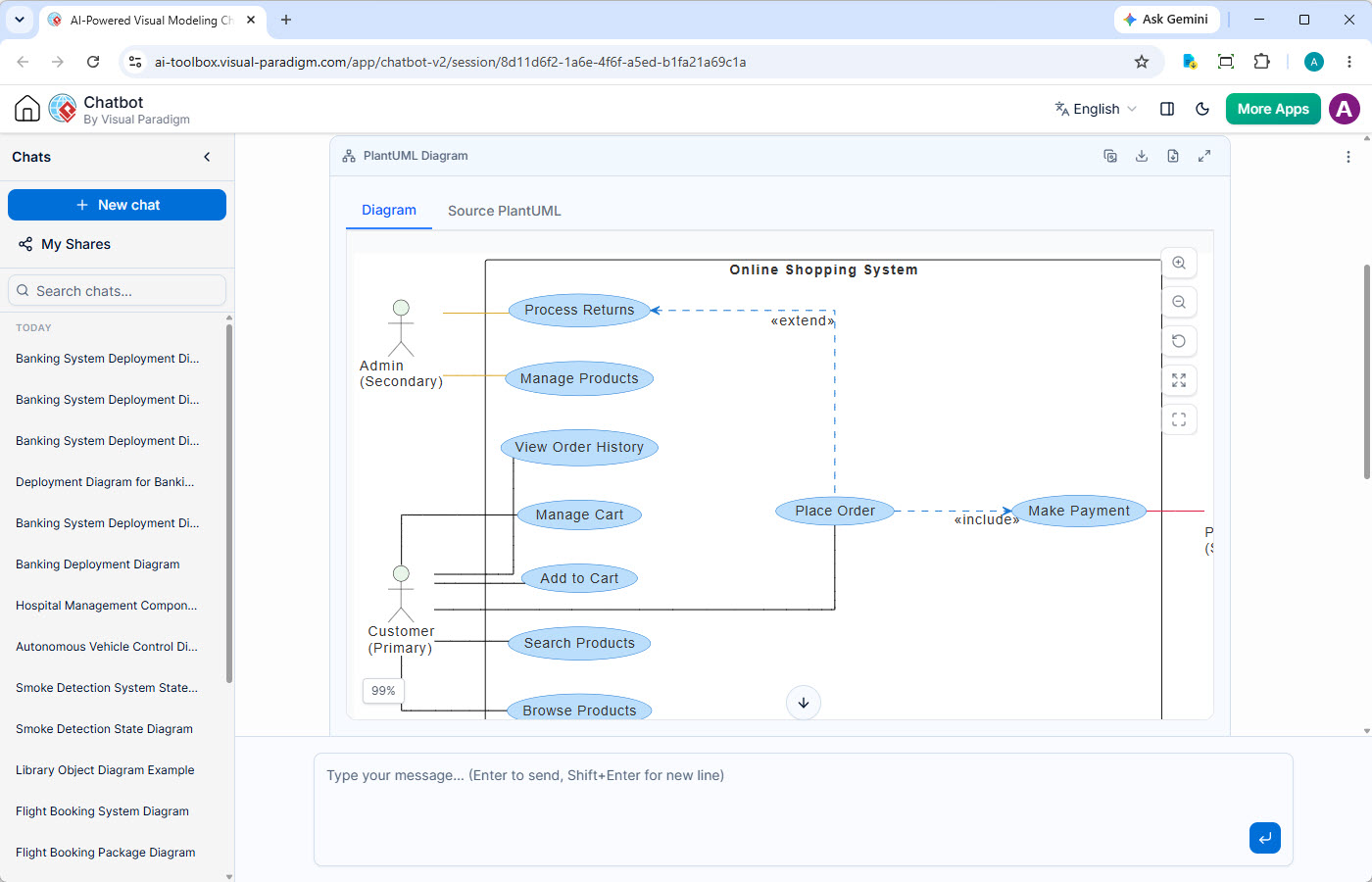
In the realm of software architecture, few diagrams are as critical for bridging the gap between business requirements and technical implementation as the UML Use Case Diagram. Based on the interface shown, we are looking at an AI-powered modeling session—specifically using the Visual Paradigm platform—to generate a comprehensive diagram for an Online Shopping System.
This tutorial explores how AI tools are revolutionizing the way we model systems, focusing on the visual representation of actors, use cases, and the crucial relationships that bind them.
1. The System Boundary and Scope
The foundation of any use case diagram is the System Boundary. In the screenshot, the large rectangle labeled Online Shopping System represents the perimeter of our software. Everything inside this box is part of the system’s functionality, while everything outside consists of external entities (Actors) that interact with the system.
- Functionality: This boundary encapsulates all the business logic, such as processing payments, managing inventory, and handling user sessions.
- Isolation: It clearly defines what the software does versus what is external. For instance, the “Payment Gateway” or the “Customer” is outside the box, interacting only through defined interfaces.
2. Identifying the Actors
The stick figures on the left side of the diagram represent Actors. An actor is an external entity that interacts with the system to achieve a specific goal. The diagram identifies two distinct user roles:
- Customer (Primary Actor): Represented by the standard stick figure. This is the primary user who initiates the core value of the system—shopping.
- Admin (Secondary Actor): Represented by the stick figure with a note. This is a “secondary” actor because they are typically involved in supporting the system (e.g., maintenance, inventory management) rather than the core transaction flow.
3. The Use Cases (Ovals)
The blue ovals represent Use Cases. Each oval is a specific task or function that the actor can perform within the system. In this Online Shopping System, we see a logical flow of actions:
- Search Products / Browse Products: The discovery phase.
- Add to Cart / Manage Cart: The selection and preparation phase.
- Place Order: The transaction phase.
- Process Returns / Manage Products: Post-transaction or administrative functions.
4. Modeling Relationships: The Logic of Interaction
The true power of a Use Case Diagram lies in the lines connecting the actors to the ovals and the ovals to each other. These lines represent relationships. The diagram effectively demonstrates two of the most important relationships in UML: Include and Extend.
The «include» Relationship
Observe the dashed line with an open arrow pointing from Place Order to Make Payment, labeled «include».
This relationship signifies mandatory behavior. If a Customer wants to “Place an Order,” the system must also “Make Payment.” You cannot have one without the other in this specific flow. It is a mechanism to avoid repetition; if “Make Payment” is required by other use cases as well, you define it once and include it wherever necessary.
The «extend» Relationship
Look at the dashed line connecting Process Returns to Place Order (or the general order context), labeled «extend».
This represents optional behavior. “Process Returns” is not part of the standard checkout flow. It only happens if a specific condition is met (e.g., a customer initiates a return request). In UML, the extending use case (Process Returns) adds behavior to the base use case only under specific circumstances.
5. From Concept to Code: The Role of AI
The screenshot displays a tab labeled “Source PlantUML.” This highlights the modern shift towards Modeling as Code. Instead of manually dragging and dropping shapes, modern AI chatbots allow users to describe their system in natural language, and the AI generates the underlying code.
For example, the AI likely generated the following PlantUML syntax to create the relationships seen above:
@startuml
left to right direction
skinparam packageStyle rectangle

actor "Customer (Primary)" as C
actor "Admin (Secondary)" as A

rectangle "Online Shopping System" {
  usecase "Browse Products" as UC1
  usecase "Search Products" as UC2
  usecase "Add to Cart" as UC3
  usecase "Manage Cart" as UC4
  usecase "Place Order" as UC5
  usecase "Make Payment" as UC6
  usecase "Manage Products" as UC7
  usecase "Process Returns" as UC8

  C --> UC1
  C --> UC2
  C --> UC3
  C --> UC4
  C --> UC5
  A --> UC7
  A --> UC8

  UC5 ..> UC6 : «include»
  UC8 ..> UC5 : «extend»
}
@enduml
6. Semantic Semantics
Why is the “Source PlantUML” tab important? It allows for version control. Because the diagram is generated from text, you can track changes in your system architecture over time using Git or similar tools. It also ensures that the visual diagram is always synchronized with the logical definition of the system.
Conclusion
The diagram shown is a classic example of how AI tools streamline the architectural process. By converting a natural language request into a structured UML diagram, tools like Visual Paradigm allow business analysts and developers to quickly validate system logic, ensuring that the “Customer” can “Place Order” and “Make Payment” before a single line of application code is written.