
Mastering DFD Levels & Decomposition: A Step-by-Step Architectural Guide
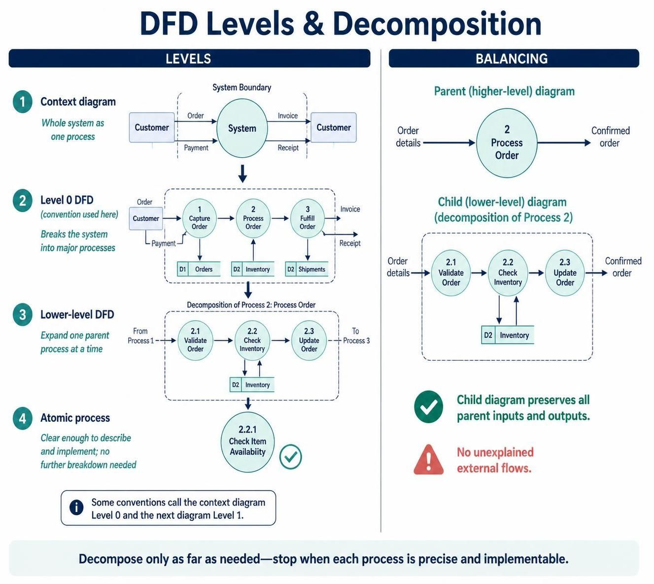
Designing a robust system architecture requires more than just writing code; it demands a clear understanding of how data moves through your application. Data Flow Diagrams (DFDs) are the blueprint for this, visualizing the flow of information from external entities to internal processes. However, a single diagram often isn’t enough to capture the complexity of a real-world system. This is where Levels and Decomposition come into play.
Using tools like Visual Paradigm, you can break down complex systems into manageable chunks. This tutorial walks you through the hierarchy of DFDs, from the high-level Context Diagram down to the atomic processes, and explains the critical rule of Balancing that ensures your architecture remains consistent.
1. The Hierarchy of System Modeling
System decomposition is the process of breaking a complex system into smaller, more understandable parts. In the world of DFDs, this is done through a structured hierarchy of levels.
Level 1: The Context Diagram
The journey begins at the highest level of abstraction. The Context Diagram (often called the Level 0 in many conventions) treats the entire system as a single, monolithic process. It answers the question: “What is the system, and who interacts with it?”
- Focus: It shows the system boundary, external entities (like Customers or Vendors), and the major data flows crossing the boundary.
- Key Feature: It does not show internal details. It is a “black box” view where the system is just one circle.
Level 2: The Level 0 DFD (System Breakdown)
The next step is to open the black box. This diagram, often referred to as the Level 0 DFD, breaks the system down into its major functional processes. While conventions vary (some call the Context Diagram Level 0), the standard practice here is to decompose the whole system into the primary functions that make it work.
- Major Processes: These are numbered 1, 2, 3, etc. (e.g., “Capture Order,” “Process Order,” “Fulfill Order”).
- Internal Data Stores: Unlike the context diagram, this level introduces data stores (D1, D2) where information is kept.
Level 3: Lower-Level DFDs (Decomposition)
As the system grows, a single major process (like “Process Order”) might be too complex to understand or implement. You must then decompose that specific process into sub-processes.
- Numbering Convention: If you decompose Process 2, its children are labeled 2.1, 2.2, and 2.3.
- Granularity: This allows you to zoom in on specific logic without cluttering the higher-level overview.
Level 4: Atomic Processes
Where do you stop? You continue decomposing until you reach an Atomic Process. An atomic process is a function that is simple enough to be described precisely and implemented directly without further breakdown. If you find yourself describing a process as “Do X, then do Y, then do Z,” you are not at the atomic level yet.
2. The Critical Rule: Balancing
When you decompose a system, it is easy to lose track of how the pieces fit together. This is where the concept of Balancing ensures integrity.
Balancing is the rule that states: The inputs and outputs of a parent process must be preserved exactly in the child (lower-level) diagram.
How Balancing Works
Imagine you have a parent process “Process Order” that takes “Order Details” as input and produces a “Confirmed Order” as output. If you decompose this into three sub-processes (Validate, Check Inventory, Update), the child diagram must still accept “Order Details” at the start and emit “Confirmed Order” at the end.
- Preservation of Flow: You cannot introduce a new external input or output in the child diagram that wasn’t present in the parent process boundary.
- Internal Transformation: While the external flows stay the same, the child diagram reveals the internal data transformations. For instance, “Order Details” might flow into “Validate Order,” get checked against “Inventory,” and eventually become a “Confirmed Order.”
3. Best Practices for Implementation
When modeling with tools like Visual Paradigm, keep these principles in mind to ensure your diagrams are useful for development:
- Don’t Over-Engineer: The exact number of levels depends on system complexity. Stop decomposing when the process is clear enough to be coded. Do not decompose every process indefinitely just for the sake of it.
- Maintain Consistency: Always double-check that your data flows match between levels. If a data store is created in Level 1, it must be referenced correctly in the Level 2 decomposition.
- Define Atomic Limits: Ensure your atomic processes are small enough to be unit-tested or implemented as a single function/method.
By mastering Levels and Decomposition, you create a modular, scalable architecture that is easy to communicate to developers and stakeholders alike.