
Introduction
In modern software engineering, architecture documentation often suffers from “documentation rot.” Diagrams created in drag-and-drop tools become stale the moment they are exported as static images, drifting away from the actual codebase. The solution lies in treating architecture as code.
The C4 model provides a practical, hierarchical way to visualize software architecture using four levels of abstraction: System Context, Containers, Components, and Code. By combining the C4 methodology with PlantUML and Diagram-as-Code workflows, teams can maintain version-controlled, highly synchronized architectural blueprints directly alongside their source code.
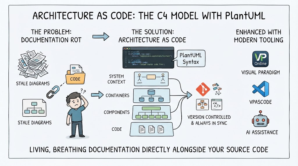
This guide explores how to implement C4 modeling using PlantUML, enhanced by modern tooling like Visual Paradigm, VPasCode, and AI Chatbots, ensuring your architecture remains a living, breathing artifact of your development process.
Key Concepts
Before diving into syntax, it is essential to understand the core pillars of this approach:
-
The C4 Hierarchy: A zoom-in metaphor inspired by digital maps. You start at the country level (Context), zoom to the city (Container), then the street (Component), and finally the building blueprint (Code).
-
Diagram-as-Code: Writing diagrams in text-based DSLs (like PlantUML) rather than drawing them. This enables diffing, merging, and CI/CD integration.
-
VPasCode: Visual Paradigm’s scripting language that bridges the gap between text-based PlantUML and the rich metadata repository of Visual Paradigm, allowing for bidirectional synchronization.
-
AI-Assisted Modeling: Leveraging Large Language Models to generate initial C4 PlantUML drafts from natural language requirements, significantly reducing the boilerplate friction.
1. Getting Started with C4-PlantUML
To use C4 models in PlantUML, you need to include the official C4 PlantUML macro definitions from the GitHub repository. This provides specialized elements like System, Container, Component, and relational connectors (Rel).
Basic Setup and Template
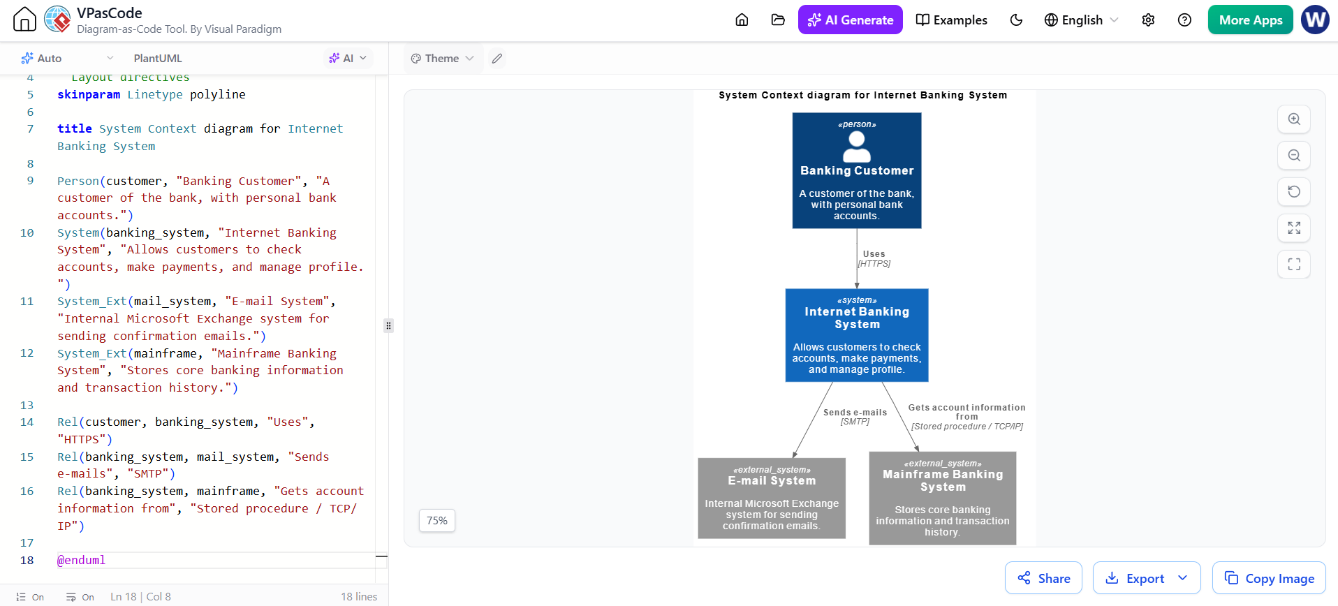
@startuml
!include https://raw.githubusercontent.com/plantuml-stdlib/C4-PlantUML/master/C4_Context.puml

' Layout directives
skinparam Linetype polyline

title System Context diagram for Internet Banking System

Person(customer, "Banking Customer", "A customer of the bank, with personal bank accounts.")
System(banking_system, "Internet Banking System", "Allows customers to check accounts, make payments, and manage profile.")
System_Ext(mail_system, "E-mail System", "Internal Microsoft Exchange system for sending confirmation emails.")
System_Ext(mainframe, "Mainframe Banking System", "Stores core banking information and transaction history.")

Rel(customer, banking_system, "Uses", "HTTPS")
Rel(banking_system, mail_system, "Sends e-mails", "SMTP")
Rel(banking_system, mainframe, "Gets account information from", "Stored procedure / TCP/IP")

@enduml
💡 Tooling Tip: While standard PlantUML renders this perfectly, importing this code into Visual Paradigm via the VPasCode editor allows you to link these abstract elements to actual UML classes or database schemas in your project repository.
2. Level 1: System Context Diagram
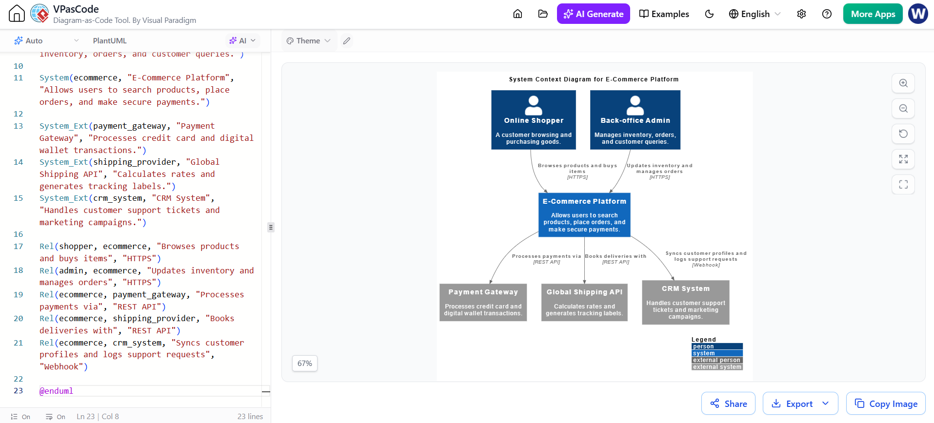
The System Context diagram sits at the highest altitude. It shows your software system as a box in the center, surrounded by its users and other software systems it interacts with.
-
Person: Represents a human user of the system.
-
System: The software system you are building.
-
System_Ext: External software systems (e.g., payment gateways, legacy mainframes, email providers).
Example: E-Commerce Platform Context
@startuml
!include https://raw.githubusercontent.com/plantuml-stdlib/C4-PlantUML/master/C4_Context.puml

LAYOUT_WITH_LEGEND()

title System Context Diagram for E-Commerce Platform

Person(shopper, "Online Shopper", "A customer browsing and purchasing goods.")
Person(admin, "Back-office Admin", "Manages inventory, orders, and customer queries.")

System(ecommerce, "E-Commerce Platform", "Allows users to search products, place orders, and make secure payments.")

System_Ext(payment_gateway, "Payment Gateway", "Processes credit card and digital wallet transactions.")
System_Ext(shipping_provider, "Global Shipping API", "Calculates rates and generates tracking labels.")
System_Ext(crm_system, "CRM System", "Handles customer support tickets and marketing campaigns.")

Rel(shopper, ecommerce, "Browses products and buys items", "HTTPS")
Rel(admin, ecommerce, "Updates inventory and manages orders", "HTTPS")
Rel(ecommerce, payment_gateway, "Processes payments via", "REST API")
Rel(ecommerce, shipping_provider, "Books deliveries with", "REST API")
Rel(ecommerce, crm_system, "Syncs customer profiles and logs support requests", "Webhook")

@enduml
AI Chatbot Integration
Instead of writing the above from scratch, you can prompt an AI Chatbot:
“Generate a C4 System Context PlantUML diagram for an e-commerce platform with shoppers, admins, a payment gateway, and a shipping provider.”
The AI will produce 90% of the correct syntax, leaving you to refine the specific relationship labels and technology protocols.
3. Level 2: Container Diagram
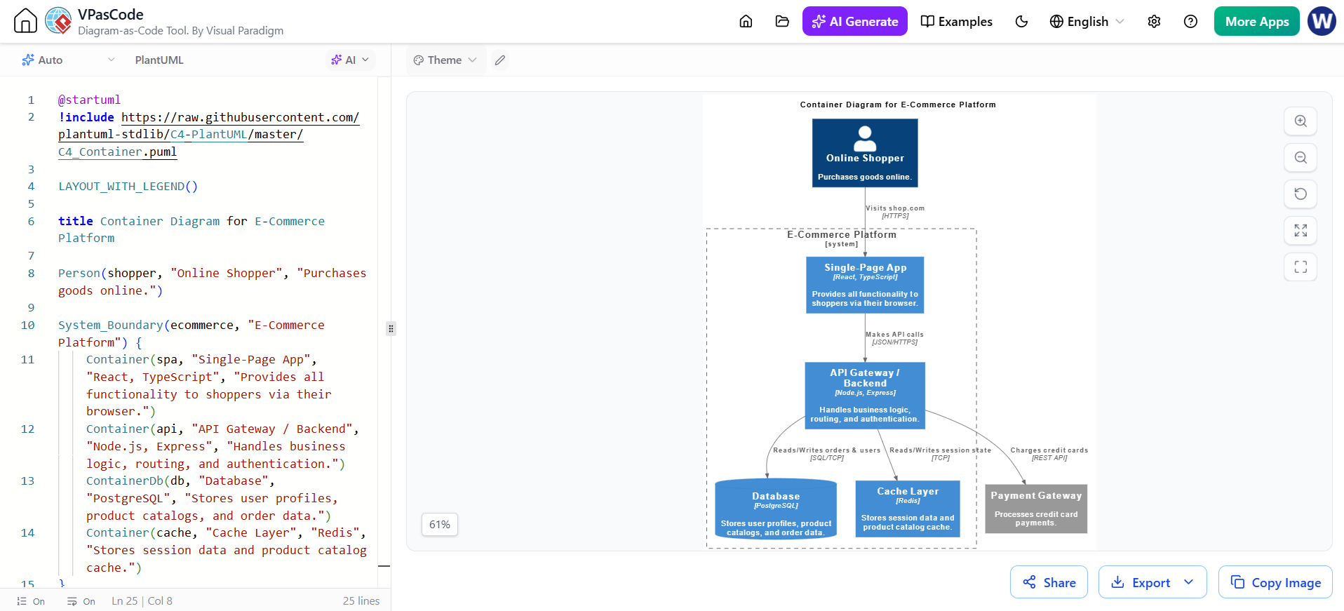
The Container diagram zooms into the software system to show the high-level technical building blocks. A “container” is a separately runnable/deployable unit (e.g., single-page application, mobile app, microservice, database, serverless function).
-
Container: An application or data store.
-
ContainerDb: A specialized container representing a database or data store.
Example: E-Commerce Containers
@startuml
!include https://raw.githubusercontent.com/plantuml-stdlib/C4-PlantUML/master/C4_Container.puml

LAYOUT_WITH_LEGEND()

title Container Diagram for E-Commerce Platform

Person(shopper, "Online Shopper", "Purchases goods online.")

System_Boundary(ecommerce, "E-Commerce Platform") {
    Container(spa, "Single-Page App", "React, TypeScript", "Provides all functionality to shoppers via their browser.")
    Container(api, "API Gateway / Backend", "Node.js, Express", "Handles business logic, routing, and authentication.")
    ContainerDb(db, "Database", "PostgreSQL", "Stores user profiles, product catalogs, and order data.")
    Container(cache, "Cache Layer", "Redis", "Stores session data and product catalog cache.")
}

System_Ext(payment_gateway, "Payment Gateway", "Processes credit card payments.")

Rel(shopper, spa, "Visits shop.com", "HTTPS")
Rel(spa, api, "Makes API calls", "JSON/HTTPS")
Rel(api, cache, "Reads/Writes session state", "TCP")
Rel(api, db, "Reads/Writes orders & users", "SQL/TCP")
Rel(api, payment_gateway, "Charges credit cards", "REST API")

@enduml
4. Level 3: Component Diagram
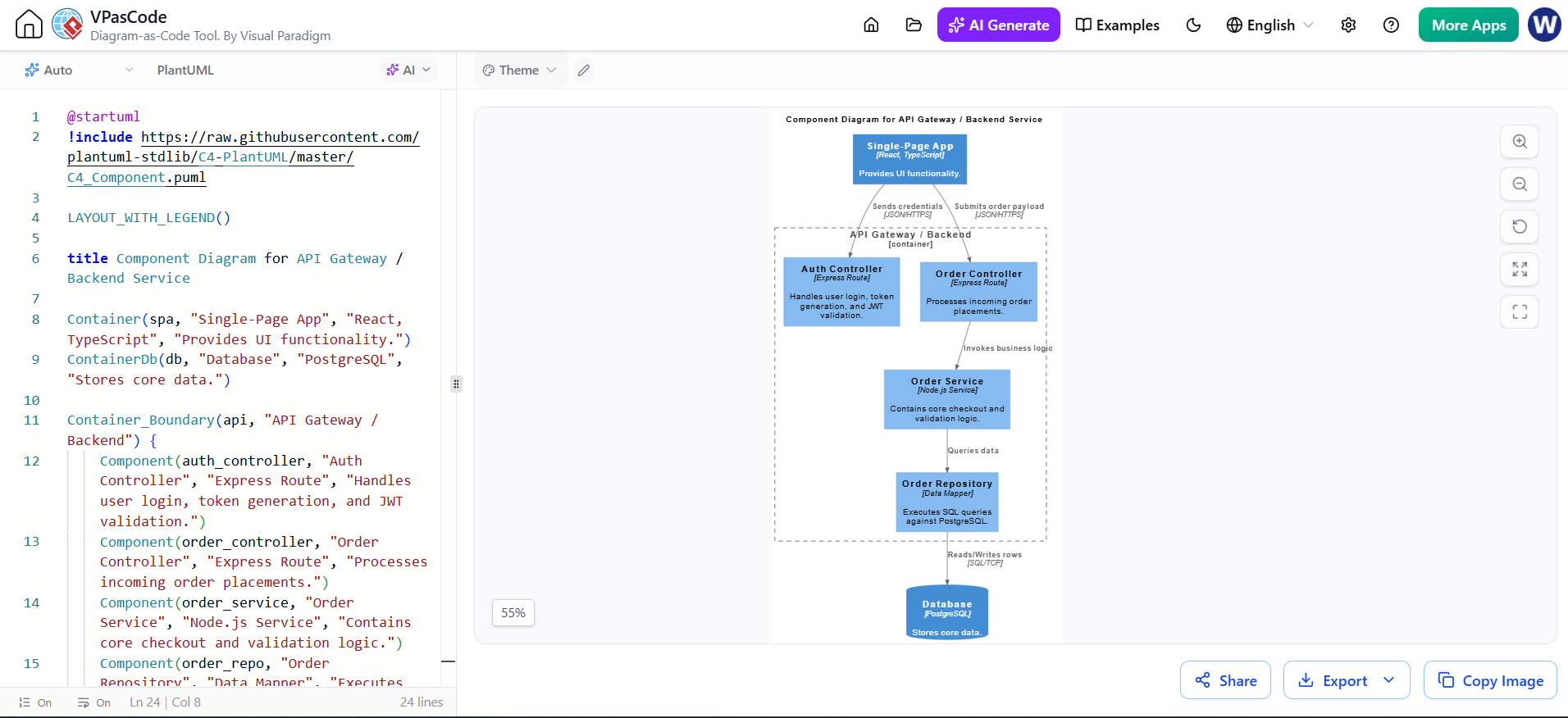
The Component diagram zooms into an individual container to show the internal components (e.g., Spring beans, modules, controllers, services) and their interactions.
Example: API Gateway Components
@startuml
!include https://raw.githubusercontent.com/plantuml-stdlib/C4-PlantUML/master/C4_Component.puml

LAYOUT_WITH_LEGEND()

title Component Diagram for API Gateway / Backend Service

Container(spa, "Single-Page App", "React, TypeScript", "Provides UI functionality.")
ContainerDb(db, "Database", "PostgreSQL", "Stores core data.")

Container_Boundary(api, "API Gateway / Backend") {
    Component(auth_controller, "Auth Controller", "Express Route", "Handles user login, token generation, and JWT validation.")
    Component(order_controller, "Order Controller", "Express Route", "Processes incoming order placements.")
    Component(order_service, "Order Service", "Node.js Service", "Contains core checkout and validation logic.")
    Component(order_repo, "Order Repository", "Data Mapper", "Executes SQL queries against PostgreSQL.")
}

Rel(spa, auth_controller, "Sends credentials", "JSON/HTTPS")
Rel(spa, order_controller, "Submits order payload", "JSON/HTTPS")
Rel(order_controller, order_service, "Invokes business logic")
Rel(order_service, order_repo, "Queries data")
Rel(order_repo, db, "Reads/Writes rows", "SQL/TCP")

@enduml
Visual Paradigm & VPasCode Advantage
While PlantUML handles layout automatically, Visual Paradigm adds enterprise value through VPasCode. When you import the Component diagram above:
-
Repository Linking: VPasCode can map
order_serviceto an actual Java class or Node.js module in your VP project. -
Impact Analysis: If you change the
Order Repositoryinterface in your code model, VP can flag the C4 diagram as outdated. -
Consistent Styling: Override PlantUML’s default skinparams with your organization’s official EA/Architecture styling templates stored in VP.
5. Best Practices for Maintaining C4 PlantUML
-
Keep Code Near Source: Store your
.pumldiagram files directly inside your repository (e.g., under a/docs/architecturefolder) so they evolve alongside your codebase. -
Leverage AI for Drafting: Use natural language prompts to generate initial PlantUML C4 blocks instantly, then refine boundaries and relationships manually.
-
Automate Rendering: Integrate PlantUML generation into your CI/CD pipeline using plugins or CLI tools to output SVG/PNG diagrams automatically to your internal wikis.
-
Hybrid Tooling Strategy: Use raw PlantUML for quick PR-level documentation, but sync critical architectural decisions to Visual Paradigm via VPasCode for long-term governance and stakeholder reporting.
-
Tagging and Metadata: Use C4 tags (
$tags="...") to enable filtering. In Visual Paradigm, these tags can drive dynamic viewpoints and compliance reports.
Conclusion
Adopting C4 modeling with PlantUML transforms architecture from a ceremonial deliverable into a continuous engineering practice. By starting with the structured abstractions of C4 and leveraging the ecosystem of AI Chatbots for rapid drafting, PlantUML for version-controlled rendering, and Visual Paradigm/VPasCode for enterprise-grade repository management, teams can achieve true architectural alignment.
The key to success is not just drawing boxes, but integrating those boxes into your development lifecycle. Start small with a System Context diagram, automate its rendering in your CI pipeline, and gradually zoom in as your team’s architectural maturity grows. Your future self—and your onboarding engineers—will thank you.