
Mastering UML Activity Diagrams with VPasCode: AI-Driven Order Workflows
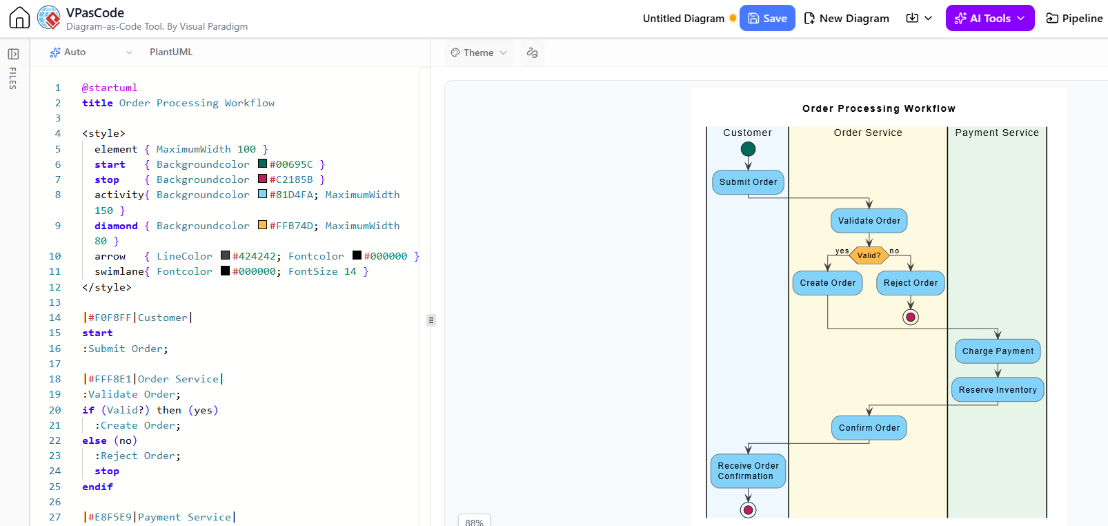
In modern software development, the gap between high-level system requirements and executable logic can often be bridged by robust modeling techniques. While traditional drag-and-drop interfaces are convenient for quick sketches, they often lack the version control and precision required for complex system specifications. This tutorial explores the concept of “Modeling as Code” using VPasCode, a tool that allows developers to define rigorous activity diagrams via text-based syntax.
We will deconstruct a specific scenario involving a Customer, an Order Service, and a Payment Service. By the end of this guide, you will understand how to structure swimlanes, implement conditional logic, and maintain a “living model” that accurately reflects your system’s behavior.
Why Use VPasCode for Activity Diagrams?
Visual Paradigm’s VPasCode (PlantUML-based) transforms the activity diagram from a static image into a version-controlled specification. Instead of manually moving boxes, you write code that describes the flow. This approach offers several distinct advantages:
- Precision: Text-based definitions eliminate alignment issues and ensure logical consistency.
- Version Control: You can commit diagram definitions to Git alongside your source code, tracking changes over time.
- Maintainability: Updating a workflow involves editing a text file rather than re-drawing complex connectors.
Step 1: Structuring the Workflow with Swimlanes
The foundation of a multi-party system diagram is the Swimlane. Swimlanes visually separate responsibilities, ensuring that every action is assigned to the correct actor or service. In the “Order Processing” scenario, we define three distinct lanes: Customer, Order Service, and Payment Service.
In VPasCode, swimlanes are defined using the pipe syntax (|LaneName|). This immediately organizes the diagram vertically, creating a clear hierarchy of responsibility.
|Customer|
|Order Service|
|Payment Service|
By defining these lanes explicitly, we ensure that the Customer initiates the request, the Order Service handles validation logic, and the Payment Service executes financial transactions. This separation prevents the common modeling error of mixing business logic with user interface actions.
Step 2: Defining Visual Styles and Logic
One of the most powerful features of VPasCode is the ability to define global styles within a <style> block. This allows you to enforce design standards—such as color coding for different process states—across the entire diagram.
In our example, we define a diamond shape for decisions and specific colors for start/stop nodes. This visual consistency helps stakeholders quickly identify the flow’s status at a glance.
Step 3: Implementing Conditional Logic
The core complexity of the order processing workflow lies in the decision-making process. When an order is submitted, the system must validate it before proceeding. This is modeled using an if statement structure.
The logic flows as follows:
- The Order Service receives the request and executes
:Validate Order;. - A decision node checks
if (Valid?). - If Yes, the flow branches to
:Create Order;. - If No, the flow branches to
:Reject Order;and terminates.
In code, this is expressed clearly using standard control flow syntax:
|Order Service|
  :Validate Order;
  if (Valid?) then (yes)
    :Create Order;
  else (no)
    :Reject Order;
    stop
  endif
Step 4: The Verification Lifecycle
Creating a diagram is only half the battle; the “Modeling as Code” approach emphasizes the importance of the Completeness and Maintenance phase. An activity diagram is a living model, not a static decoration.
When reviewing the diagram, you must check for:
- Dead Ends: Ensure that every start node leads to a meaningful outcome. There should be no paths where the flow stops unexpectedly without a decision or error state.
- Consistency: The diagram must agree with the written use cases. If the text specification says “Retry on failure,” but the diagram simply stops at an error, the model is inconsistent.
- Screen Navigation vs. Process Flow: Avoid modeling “Click Next Button” unless that specific interaction is the focus. Instead, model the logical outcome, such as “Proceed to Payment.”
Conclusion
By following these guidelines—keeping goals visible, maintaining consistent detail, labeling decisions, and using swimlanes for responsibility—you transform an activity diagram from a simple flowchart into a rigorous system specification. Whether you are drawing manually or generating code with VPasCode, the logic remains the same: clarity, robustness, and precision.