
Mastering Manufacturing Loops: AI-Driven Flowchart Rework with PlantUML
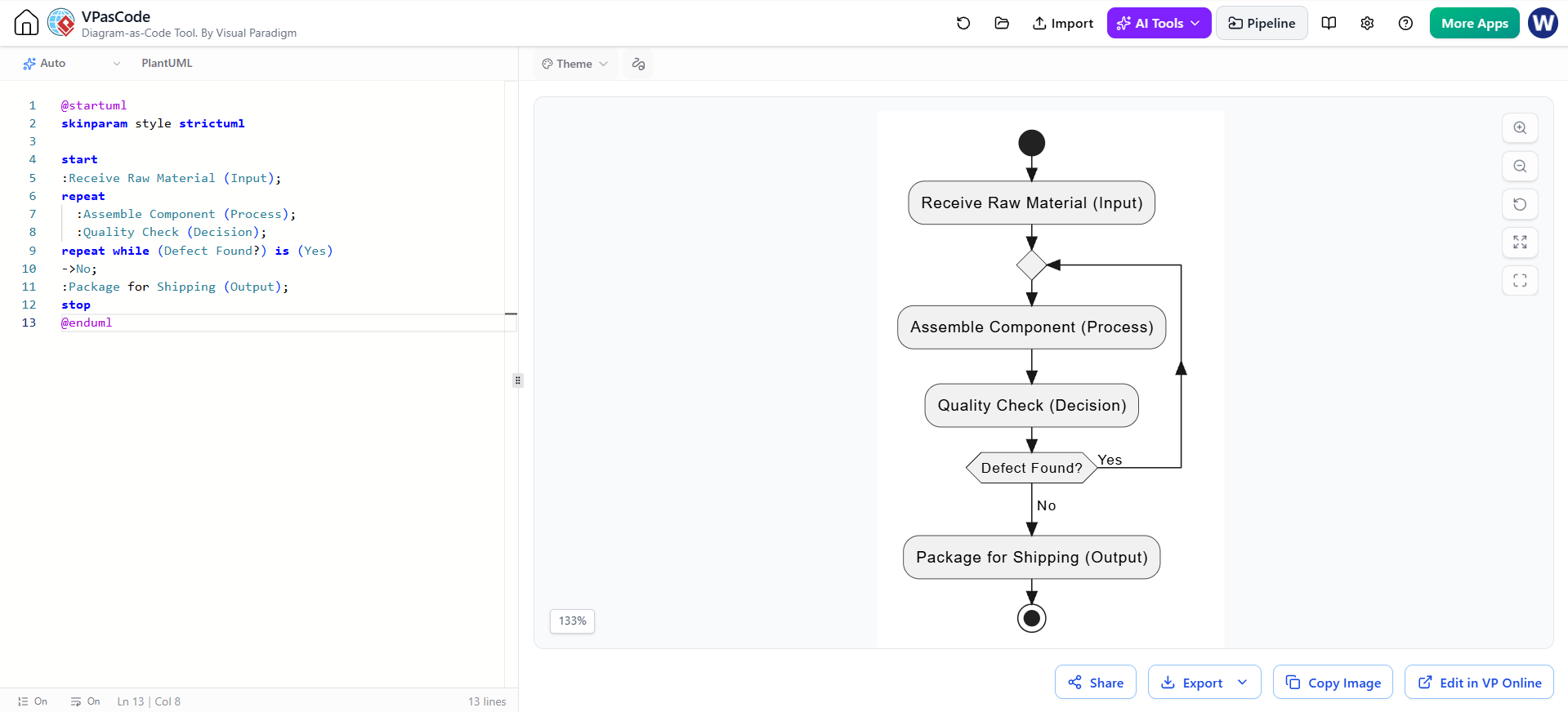
In the world of systems engineering and software development, visualizing complex workflows is essential for clear communication. One of the most common scenarios involves a manufacturing process where a defect might trigger a rework cycle. This tutorial will guide you through understanding and modeling a Manufacturing Workflow using PlantUML within the VPasCode tool.
We will deconstruct the logic of a loop, specifically how to handle “rework” scenarios where a quality check forces the system to go back to a previous step. This example demonstrates the power of Diagram-as-Code, allowing you to define logic textually and render it instantly.
1. The Core Concept: The Rework Loop
Before diving into the syntax, let’s analyze the logic flow represented in the diagram. A manufacturing line typically follows a linear path, but real-world quality assurance often introduces branching logic.
In this specific workflow, we have a While Loop structure. Here is the logical breakdown:
- Input: The process begins by receiving raw materials.
- Process: The components are assembled.
- Decision: A quality check is performed. This is the pivot point of our diagram.
- Branching:
- If a defect is Found (Yes): The flow must loop back to the assembly stage.
- If No Defect is found: The flow proceeds to packaging.
Understanding this “rework” loop is critical. In many modeling tools, drawing this loop requires manually drawing arrows that cross over other lines. In VPasCode, we simply describe the condition, and the tool handles the geometry.
2. Analyzing the VPasCode Code
Let’s examine the specific PlantUML code provided in the editor. This code uses standard Activity Diagram syntax to define the flow.
@startuml
skinparam style strictuml

start
:Receive Raw Material (Input);
repeat
  :Assemble Component (Process);
  :Quality Check (Decision);
repeat while (Defect Found?) is (Yes)
->No;
:Package for Shipping (Output);
stop
@enduml
Key Syntax Components
The code is concise and readable. Here is what each line accomplishes:
Initialization
We start with @startuml to define the block. The skinparam style strictuml ensures the diagram adheres to strict UML standards, resulting in the clean, professional look seen in the rendering.
The “Repeat…While” Block
This is the heart of the tutorial. The loop is defined using the repeat keyword:
repeat
  :Assemble Component (Process);
  :Quality Check (Decision);
repeat while (Defect Found?) is (Yes)
This structure tells the renderer: “Execute these steps at least once, and continue to execute them while the condition ‘Defect Found?’ is true.”
The Exit Path
Once the loop condition is false (i.e., no defect is found), the code uses ->No; to define the path that exits the loop and continues the linear flow.
3. Visualizing the Logic Flow
When rendered, the VPasCode tool interprets the text and generates the flowchart automatically. Notice the diamond shape representing the decision point.
- Start Node: The black circle marks the beginning.
- Input Action: The flow moves to Receive Raw Material.
- The Loop Entry: The arrow from the decision point feeds back into the Assemble Component step if the condition is met.
- The Decision: The diamond labeled Defect Found? directs the flow.
- Loop Exit: The arrow labeled No leads to Package for Shipping.
- End Node: The final black circle with a ring indicates the end of the process.
This visual representation clarifies the logic better than a paragraph of text ever could. It allows stakeholders to instantly see where the bottlenecks (the rework loop) might be.
4. Best Practices for Modeling Loops
When creating similar diagrams in VPasCode or other diagram-as-code tools, keep these architectural principles in mind:
- Explicit Inputs and Outputs: As seen in the labels “(Input)” and “(Output)”, clearly defining the boundaries of your system helps in understanding data flow.
- Descriptive Labels: The decision logic
(Defect Found?) is (Yes)is explicit. Always ensure your loop conditions are readable. - Modularity: By using
repeat, we modularize the assembly process. If the assembly process changes, the loop logic remains intact.
Conclusion
By leveraging VPasCode, you transform complex workflow logic into clean, maintainable code. This Manufacturing Workflow example demonstrates how easy it is to model conditional logic and loops without the drag-and-drop headaches of traditional diagramming tools. Whether you are mapping software algorithms or industrial assembly lines, mastering these PlantUML structures is a vital skill for any technical architect.