
Mastering UML Use Case Diagrams with VPasCode
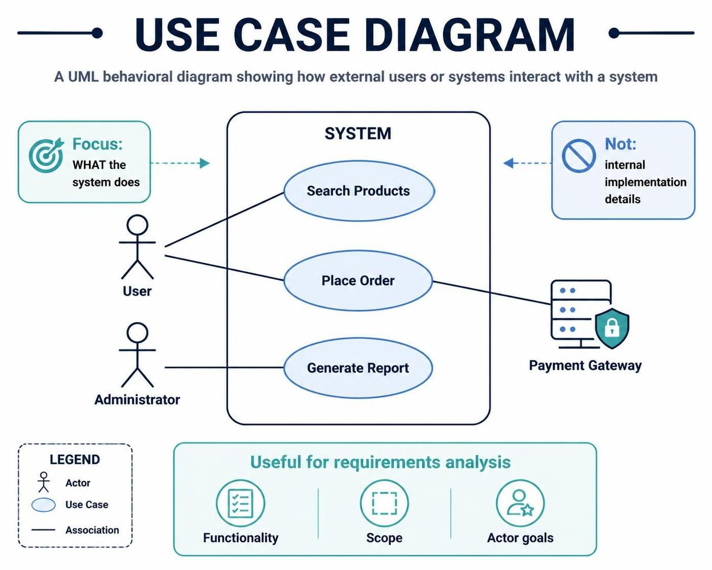
In the world of software engineering and system architecture, clarity is paramount. Before a single line of code is written, architects and developers must understand what the system needs to do. This is where the Use Case Diagram comes into play. As a foundational UML behavioral diagram, it acts as a bridge between the technical team and stakeholders, translating abstract requirements into a visual narrative.
Based on industry standards and tools like Visual Paradigm, this tutorial breaks down the anatomy, purpose, and construction of a Use Case Diagram, ensuring you can effectively communicate your system’s scope.
What is a Use Case Diagram?
A Use Case Diagram is a high-level representation of the functional requirements of a system. Its primary goal is to illustrate how external users or systems (known as actors) interact with the system under construction.
Unlike other diagrams that focus on internal mechanics, data structures, or class hierarchies, the Use Case Diagram focuses strictly on what the system does from the perspective of the actor. It deliberately ignores internal implementation details, making it the ideal tool for requirements analysis and defining the boundaries of your project.
Core Components and Notation
To read or create a Use Case Diagram, you must understand its three fundamental elements: Actors, Use Cases, and Relationships.
1. Actors
Actors represent the roles played by users or external systems that interact with your application. In the diagram, they are typically depicted as stick figures.
- Human Actors: These represent real users. Examples include a “User,” “Administrator,” “Cashier,” or “Manager.”
- System Actors: These represent other software systems or hardware devices. For instance, in an e-commerce platform, a “Payment Gateway” or a “Shipping API” would be modeled as actors.
2. Use Cases
A Use Case represents a specific goal or function that an actor wants to achieve. In the diagram, these are represented as ovals located inside the system boundary.
- Examples: “Search Products,” “Place Order,” “Generate Report,” or “Log In.”
- Scope: Each use case should describe a discrete unit of functionality.
3. The System Boundary
The large rectangle containing the use cases represents the System Boundary. Everything inside the box is part of the system’s functionality. Anything outside the box is an external entity (actor).
4. Associations (Links)
Lines connecting Actors to Use Cases are called Associations. They indicate that the actor initiates or participates in that specific use case. The line represents the flow of control or information between the actor and the system.
Visualizing Interactions: A Step-by-Step Analysis
Let’s break down a typical scenario using the logic found in the diagram provided. Imagine an E-Commerce System.
The Human Interaction
On the left side of the system boundary, you will typically find human actors.
- The User actor connects to “Search Products” and “Place Order.” This tells us that a customer can browse the catalog and purchase items.
- The Administrator actor connects to “Generate Report.” This indicates that administrative duties are separate from customer-facing features.
The External System Interaction
Use Case Diagrams are powerful because they don’t just show human users; they show integration points.
- Notice the Payment Gateway on the right side. It is an external system actor.
- It connects to the “Place Order” use case. This is critical: it visually communicates that the “Place Order” function is not self-contained. It relies on an external dependency (the Payment Gateway) to complete the transaction.
Common Relationships
While the diagram shows simple associations, advanced modeling often includes relationships between use cases:
- Includes: A mandatory relationship where one use case must contain the functionality of another. For example, “Place Order” includes “Login” (you cannot order without logging in).
- Extends: An optional relationship. For example, “Place Order” might be extended by “Apply Discount” (only if the user has a coupon).
- Generalization: A relationship where one actor or use case is a specialized version of another (e.g., a “Premium User” is a type of “User”).
Best Practices for Modeling
To create an effective Use Case Diagram, follow these guidelines:
- Focus on Goals, Not Actions: A Use Case should represent a goal. Instead of naming a use case “Enter Data,” name it “Register Account.”
- Keep it High-Level: Do not detail the internal steps of a use case here. Save the workflow diagrams for later. This diagram is for defining scope.
- Define the Boundary Clearly: Ensure the system boundary is clear. If a feature is outside the box, it belongs to the actor, not the system.
- Use Clear Labels: Actors should be labeled by their role (e.g., “Customer”), not their name (e.g., “John Doe”).
Why Use Case Diagrams Matter
As noted in the diagram legend, these models are incredibly useful for requirements analysis. They provide a visual contract between the business stakeholders and the development team.
By clearly delineating Functionality (what the system does), Scope (what is included in the build), and Actor Goals (why the system exists), you ensure that the project team is aligned before the actual development begins. Whether you are building a simple web app or a complex enterprise system, the Use Case Diagram is your first step toward a well-architected solution.