
Mastering MVC Sequence Diagrams: Architecting Schedule Inspections with UML
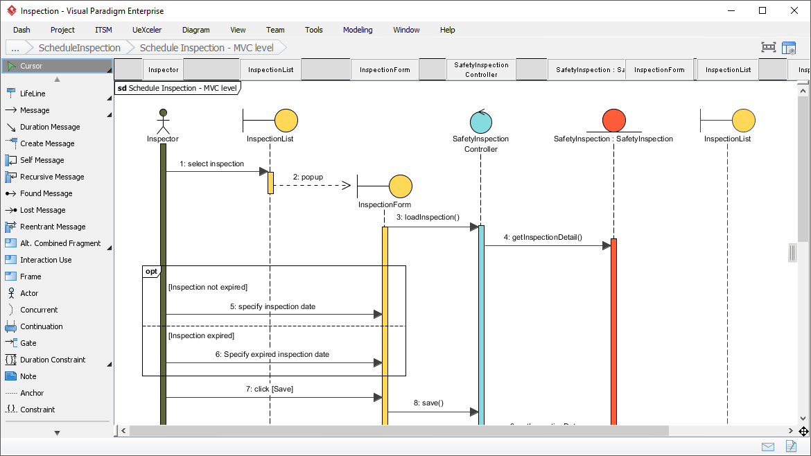
In the realm of software engineering, moving from abstract requirements to concrete implementation requires a clear map. While Class Diagrams define the structural skeleton of your system, Sequence Diagrams provide the dynamic behavior—the “blood flow” of the application. Using tools like Visual Paradigm, we can visualize complex interactions like the “Schedule Inspection” workflow, ensuring that our Model-View-Controller (MVC) architecture functions seamlessly.
This tutorial dissects a specific system architecture scenario: Schedule Inspection. We will explore how an Inspector interacts with the system to configure and save inspection details, breaking down the interaction between the User, the View (UI), and the Controller (Logic).
Understanding the MVC Interaction Pattern
The diagram provided in our context follows the classic MVC (Model-View-Controller) pattern, a design pattern widely used in web and enterprise applications to separate concerns. The Sequence Diagram visualizes how these layers communicate over time.
1. The Actor (The User)
At the far left, we see the Inspector. In UML, this is represented by an Actor stick figure. This role initiates the process. They are the human element triggering the system’s logic.
2. The View Layer (Presentation)
The system responds with two key view components:
- InspectionList (View): This component displays a list of available inspections to the user.
- InspectionForm (View): This is a popup or form interface where the user inputs specific data (like dates).
3. The Controller Layer (Logic)
The SafetyInspection Controller acts as the traffic cop. It receives requests from the View, processes data, and interacts with the underlying data (Model). In this diagram, it orchestrates the flow between the user interface and the data retrieval processes.
Step-by-Step Workflow Analysis
The sequence diagram is read from top to bottom, representing the passage of time. Let’s trace the message flow that constitutes the “Schedule Inspection” logic.
- Selection (Message 1): The Inspector selects an inspection from the list. The
select inspectionmessage is sent to the InspectionList. - UI Transition (Message 2): The InspectionList triggers a
popupaction, which opens the InspectionForm. This is a crucial UI interaction where the system shifts focus to data entry. - Data Retrieval (Message 3 & 4):
- The InspectionForm requests data by sending
loadInspection()to the SafetyInspection Controller. - The Controller then queries for specific details via
getInspectionDetail().
- The InspectionForm requests data by sending
- Conditional Logic (Messages 5 & 6): The diagram introduces a critical decision point regarding the inspection status.
- Scenario A (Not Expired): If the inspection is valid, the Inspector specifies the standard inspection date.
- Scenario B (Expired): If the inspection has expired, the Inspector must specify an expired inspection date.
- Submission (Message 7): Once the details are entered, the Inspector clicks [Save].
- Persistence (Message 8): The InspectionForm sends a
save()command to the Controller, finalizing the transaction.
Deep Dive: The Opt Combined Fragment
One of the most powerful features in UML Sequence Diagrams is the Combined Fragment. In the “Schedule Inspection” diagram, you will see a box labeled opt with a dashed line separating two conditions.
This stands for Optional. It indicates that the actions inside the box are not mandatory in every execution, or rather, one of the internal blocks must occur based on a specific condition.
Let’s look at the logic defined within the opt frame:
Frame: opt
  Condition: [Inspection not expired]
    Action: 5: specify inspection date

  Condition: [Inspection expired]
    Action: 6: Specify expired inspection date
This structure is vital for business logic validation. It forces the developer to handle edge cases. The system cannot proceed to “Save” without determining the status of the inspection. The opt frame ensures that the code generated from this diagram will include an if/else statement to handle these two distinct states.
Why Use Sequence Diagrams for API Definition?
The text context highlights that Sequence Diagrams are perfect for “API Interface Definition.” Why?
In the diagram, the horizontal arrows represent method calls. For example, loadInspection() or save(). When developers use this diagram as a blueprint:
- They know exactly what methods need to exist in the Controller class.
- They understand the order of operations (synchronous vs asynchronous).
- They can define the parameters required (e.g., the “inspection date” argument).
Without this diagram, the Controller might be built without the necessary getInspectionDetail method, or the View might try to save data before the Controller has loaded the necessary context.
Conclusion
The “Schedule Inspection” sequence diagram is more than just a drawing; it is a logical contract between the user interface and the backend logic. By visualizing the interaction between the Inspector, InspectionForm, and SafetyInspection Controller, we ensure that the application handles both standard and expired inspection scenarios correctly.
Whether you are in the detailed design phase or defining API endpoints, this step-by-step visualization guarantees that the system is robust, logical, and ready for implementation.