Mastering Authentication Workflows with PlantUML in VPasCode
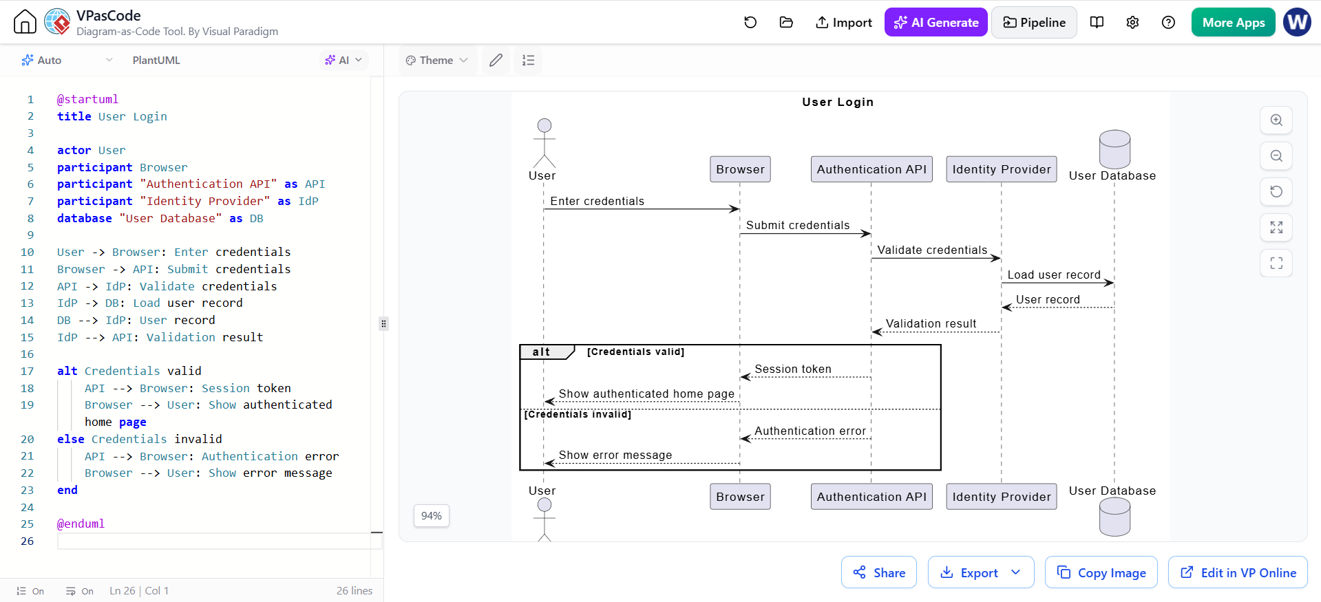
In modern software engineering, the ability to visualize complex system interactions is as critical as the code itself. One of the most powerful tools for this purpose is the Sequence Diagram, which maps out the interactions between different system components over time. In this tutorial, we will explore how to model a robust User Login workflow using PlantUML within the Visual Paradigm as Code (VPasCode) editor. This approach combines the precision of diagramming with the version control benefits of text-based modeling.
Understanding the Architecture: The Login Lifecycle
Before writing a single line of code, it is essential to understand the logical flow of an authentication process. The diagram provided in our context illustrates a classic “Federated Authentication” pattern. Here is the breakdown of the actors and participants involved:
- User (Actor): The human initiating the request.
- Browser (Client): The interface through which the user interacts.
- Authentication API (Gateway): The service handling the initial request and managing the session.
- Identity Provider (IdP) & Database (DB): The backend services responsible for verifying credentials and storing user data.
The flow moves sequentially from the user entering credentials to the API validating them against the IdP. This separation of concerns—where the API delegates validation to the IdP—is a best practice for scalability and security.
Building the Diagram: A Step-by-Step Guide
VPasCode allows you to define your entire architecture using text. This makes it incredibly easy to refactor, version, and share your designs. Let’s walk through the specific syntax used in the example.
1. Defining Participants
The first step is to declare the “actors” in your system. PlantUML uses specific keywords to differentiate between human actors, software components, and databases.
title User Login
actor User
participant Browser
participant "Authentication API" as API
participant "Identity Provider" as IdP
database "User Database" as DB
Notice how we use as to define aliases (e.g., as API). This keeps the rest of your code concise while allowing descriptive names in the visual representation.
2. Mapping the Request Lifecycle
Once participants are defined, we map the messages using arrows. The syntax A -> B: Message denotes a synchronous call, while A --> B: Message denotes a return or asynchronous message.
User -> Browser: Enter credentials
Browser -> API: Submit credentials
API -> IdP: Validate credentials
IdP -> DB: Load user record
DB --> IdP: User record
IdP --> API: Validation result
3. Handling Logic with Alt/Opt Blocks
Real-world systems almost always involve conditional logic (e.g., success vs. failure). PlantUML handles this elegantly with the alt block. This is crucial for documenting the “Happy Path” and the “Error Path” simultaneously.
alt Credentials valid
    API --> Browser: Session token
    Browser --> User: Show authenticated home page
else Credentials invalid
    API --> Browser: Authentication error
    Browser --> User: Show error message
end
The alt block allows you to define alternative execution paths based on specific conditions. In this case, the system branches based on whether the credentials are valid or not.
Why Use VPasCode for Diagramming?
Using a tool like VPasCode transforms diagramming from a static drawing exercise into a dynamic coding task. By writing the diagram as code, you gain several advantages:
- Version Control: You can track changes to your architecture over time using Git, just like your application code.
- Consistency: Tools like AI-assisted generation ensure that naming conventions and syntax remain consistent across large projects.
- Speed: It is often faster to type
User -> Browserthan to drag and drop boxes and draw lines on a canvas.
Conclusion
By leveraging the text-based syntax of PlantUML within VPasCode, developers and architects can create precise, maintainable, and scalable documentation. Whether you are mapping a simple login flow or a complex payment workflow, the principles of defining participants, mapping messages, and handling logic remain the same. Start writing your diagrams as code today to improve your system’s clarity and your team’s collaboration.