
Mastering Use-Case Modeling with VPasCode: From Code to System Architecture
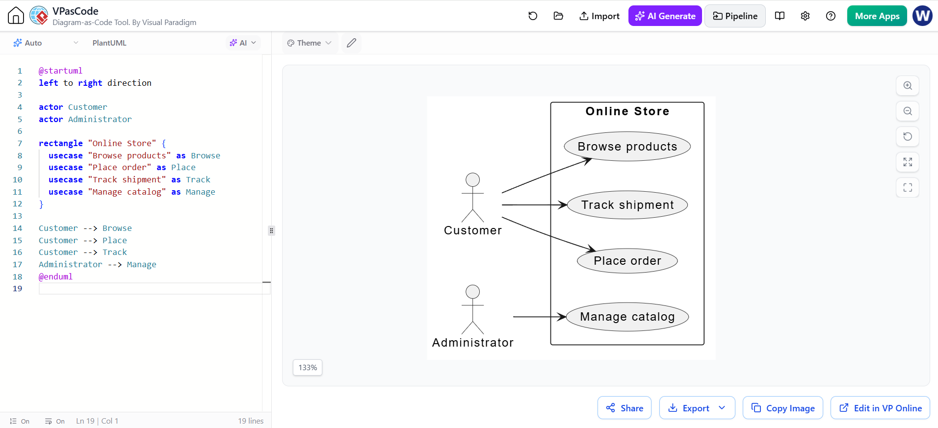
In the realm of software engineering, visualizing the interaction between users and a system is critical for defining requirements. Use-case diagrams serve as the blueprint for this interaction, identifying actors (who interacts) and system capabilities (what the system does). Modern tooling like VPasCode (Visual Paradigm as Code) allows us to define these complex architectural relationships using plain text, ensuring version control and rapid prototyping.
Understanding the Core Components
A use-case diagram is composed of three fundamental elements. In the context of our “Online Store” example, we see these clearly defined:
- Actors: These represent the external entities interacting with the system. They are typically depicted as stick figures.
- Customer: The primary user engaging in shopping behaviors.
- Administrator: The backend user responsible for system maintenance.
- System Boundary: A rectangle that encapsulates the scope of the system. In our diagram, the
rectangle "Online Store"defines what is inside the system versus what is outside. - Use Cases: Represented as ovals or ellipses, these are the specific functions or goals the system performs.
- Customer Use Cases: Browse products, Place order, Track shipment.
- Administrator Use Cases: Manage catalog.
Decoding the VPasCode Syntax
Using a text-based approach to diagramming offers precision and speed. Below is the breakdown of the specific PlantUML syntax used to generate the “Online Store” architecture.
1. Defining Direction and Actors
First, we set the layout direction for the diagram and define the actors outside the system boundary.
@startuml
left to right direction

actor Customer
actor Administrator
2. Defining the System Boundary
The rectangle command creates the system boundary. We give it a label (“Online Store”) and use curly braces { } to define the scope of the content within it.
rectangle "Online Store" {
  usecase "Browse products" as Browse
  usecase "Place order" as Place
  usecase "Track shipment" as Track
  usecase "Manage catalog" as Manage
}
Notice the use of as to assign aliases (like Browse). This allows us to reference the use case later without repeating the full text string.
3. Establishing Relationships
Finally, we link the actors to their respective use cases using arrows. The syntax Actor --> UseCaseAlias creates a directed association.
Customer --> Browse
Customer --> Place
Customer --> Track
Administrator --> Manage
Visualizing the Architecture
When the VPasCode engine processes this text, it renders a clean architectural view. The Customer is shown connected to the operational flow (browsing, ordering, tracking), while the Administrator is isolated to the management flow (catalog management). This separation of concerns is vital for system design, as it clearly delineates user roles.
Why Use Text-Based Modeling?
Traditional GUI modeling tools can sometimes struggle with version control, as binary diagram files are difficult to diff. By using VPasCode:
- Version Control Friendly: You can track changes to your system architecture in Git just like you would with source code.
- AI Integration: Tools like VPasCode allow for AI-assisted generation, where you can describe a feature in natural language, and the tool generates the corresponding code blocks.
- Portability: The diagram code is portable and can be rendered by any standard PlantUML engine, not just the proprietary Visual Paradigm software.
Mastering these syntax rules empowers you to rapidly prototype system architectures and communicate complex requirements effectively.