Mastering BPMN Choreography: Modeling Inter-Organizational Workflows
In the complex landscape of enterprise architecture, understanding how different organizations interact is just as critical as understanding internal processes. This is where Choreography Diagrams in Business Process Model and Notation (BPMN) become essential. Unlike standard flow diagrams that focus on a single entity’s internal logic, choreography diagrams focus on the “handshake”—the public interactions between two or more business entities.
In this tutorial, we will deconstruct a real-world logistics scenario depicted in a BPMN Choreography diagram. We will walk through the modeling concepts, the specific notation used to represent the “Consolidator” role, and how to structure these diagrams using Visual Paradigm.
Understanding the Core Concept: The Public vs. Private
The primary advantage of a Choreography Diagram is its ability to model the interaction between parties without revealing their internal private processes. Imagine a supply chain involving a Retailer, a Consignee, and a Carrier. In a standard Process Diagram, you would have to map out exactly how the Retailer calculates their inventory to know when to order. In a Choreography Diagram, the Retailer is represented simply as a “Lane,” and the focus is strictly on the message exchange.
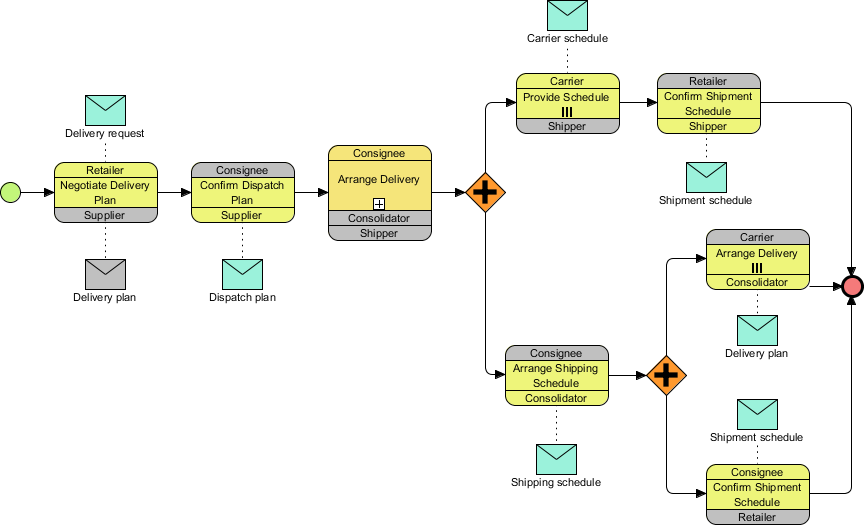
As shown in our reference diagram, the process is divided into vertical lanes representing different entities:
- Business Entities: These are the participants (e.g., Retailer, Consignee, Supplier, Carrier, Consolidator).
- Interaction Flow: Arrows between lanes represent messages (e.g., “Delivery request,” “Shipment schedule”).
- Message Flow: The envelope icons represent the data payload being exchanged.
Deconstructing the Logistics Workflow
Let’s break down the logical flow of the diagram provided, which models a complex delivery scheduling process.
Phase 1: The Negotiation Sequence
The process begins on the left with the Retailer and Supplier. This phase represents the initial agreement.
- Initiation: The Retailer initiates a “Delivery request” (represented by the teal envelope) to the Supplier.
- Response: The Supplier responds with a “Delivery plan.”
- Verification: The flow moves to the Consignee and Supplier to “Confirm Dispatch Plan.” Here, the Consignee validates the plan and sends back a “Dispatch plan.”
Phase 2: The Consolidation Logic
This is the most technically interesting part of the diagram. We see a lane labeled Consolidator interacting with the Consignee.
The task Arrange Delivery is performed by the Consignee, but the diagram explicitly shows a Consolidator role within that same vertical space. This is a powerful modeling technique. In BPMN, you can use multiple roles within a single lane or utilize specific sub-process elements to show that while the Consignee is the primary actor, the Consolidator is the specialized entity executing the logistics arrangement.
Phase 3: Parallel Gateway Logic (The Fork)
Once the delivery arrangement is made, the diagram encounters a yellow diamond with a plus sign (+). This is a Parallel Gateway.
- Function: It splits the single flow into two simultaneous branches.
- Branch A (Top): Involves the Carrier and Retailer confirming shipment schedules.
- Branch B (Bottom): Involves the Consignee and Consolidator arranging the shipping schedule.
Both branches must complete successfully for the process to proceed. This is indicated by the synchronization of the two flows back into a single path.
Modeling Syntax and Notation Rules
When creating diagrams like this in Visual Paradigm or similar tools, specific syntax rules apply to ensure the diagram remains valid BPMN.
1. Defining the Participants
Every vertical lane represents a participant. You must define the Start Event (the green circle) within the lane that initiates the interaction. In this diagram, the Retailer is the initiator.
2. Message Flows vs. Sequence Flows
It is crucial to distinguish between the two types of arrows:
- Sequence Flow (Solid Arrow): Represents the order of execution within a specific entity’s logic.
- Message Flow (Dashed Line): Represents the transfer of data between entities. Note: In BPMN Choreography, Message Flows are often represented as solid lines connecting the interaction points, but conceptually they act as the “handshake” between the lanes.
3. Handling Complex Roles
In the diagram, you will notice the Consolidator is stacked below the Consignee in the same task block. This implies a delegation or a shared responsibility model where the Consignee outsources the specific “Arrange Delivery” task to the Consolidator.
Why Use This Model?
Using a Choreography Diagram for this logistics process offers significant benefits:
- Privacy: The Carrier does not need to know the Retailer’s internal inventory levels; they only need to know the “Shipment schedule.”
- Clarity: It clearly visualizes the dependencies. For example, the Carrier cannot confirm the schedule until the Consignee has arranged the delivery.
- Scalability: If a new entity (e.g., a Customs Broker) is added, it can be inserted as a new lane without breaking the existing flow logic of the Retailer or Carrier.
Conclusion
Choreography Diagrams are the bridge between isolated business processes. By focusing on the “handshake” rather than the internal machinery, they allow organizations to collaborate efficiently without exposing sensitive operational details. Whether you are mapping a simple customer-vendor interaction or a complex multi-party logistics chain, the principles of clear participant definition and message flow remain the same.
Next time you model a system architecture, ask yourself: Does this interaction involve multiple parties? If so, a Choreography Diagram might be the missing piece in your documentation strategy.