
C4 Diagram Validation: Ensuring Clarity for AI and Chatbot Architecture
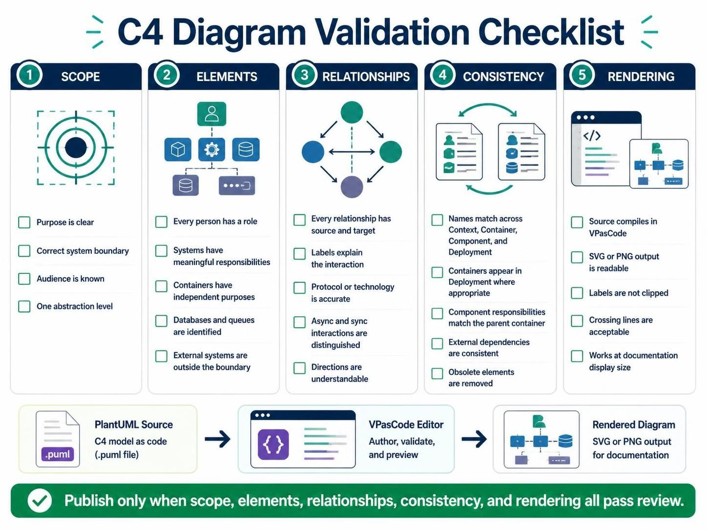
Creating a software architecture diagram is an act of translation. You are translating complex, often messy codebases into a visual language that stakeholders can understand. However, a diagram is only as good as its accuracy and clarity. Before you ever hit the “Publish” button or share a link with your team, you need a rigorous quality assurance process.
The C4 Diagram Validation Checklist provides a structured framework to ensure your diagrams are not just pretty pictures, but accurate representations of your system. This guide walks you through the five critical levels of validation: Scope, Elements, Relationships, Consistency, and Rendering.
1. Scope: The Foundation of Your Model
Before you worry about specific boxes and lines, you must validate the “why” and “who” of your diagram. A diagram that tries to do too much is a diagram that explains nothing.
- Is the diagram’s purpose clear? Are you trying to explain how the system works to a developer, or how it fits into the enterprise to a manager? The answer determines your level of detail.
- Is the correct system boundary shown? In C4, the boundary separates what you own from what you don’t. Ensure your context is clearly defined.
- Is the audience known? A diagram for a DevOps engineer needs different information (infrastructure) than one for a Product Manager (features).
- Is the diagram showing one abstraction level? This is a cardinal rule. Do not mix high-level business context with low-level database implementation in the same view.
2. Elements: The Building Blocks
Once the scope is set, you must inspect the individual components of your diagram. Every element must have a distinct reason for existing.
People and Roles
Does every person icon represent a distinct role? Avoid generic “User” labels if you can help it. A “Customer” is different from an “Administrator.”
Systems and Containers
Meaningful Responsibility: Does the system or container have a single, clear purpose? A “Web Server” is a generic element; a “Payment Processing Gateway” is a meaningful one.
Identification: Are databases and queues correctly identified? Don’t hide a critical queue behind a generic box. Make the data flow explicit.
External Systems: Ensure that external systems (like Stripe, AWS, or Google) are placed outside your system boundary. This reinforces the concept of ownership.
3. Relationships: The Lines That Matter
The connections between your elements tell the story of data flow. If the lines are confusing, the diagram is useless.
- Source and Target: Every relationship must have a clear start and end point. Avoid lines that float in mid-air.
- Descriptive Labels: Never leave a relationship unlabeled. The label should explain the interaction, not just the protocol. Instead of “HTTP,” use “Retrieves Order Details via HTTP.”
- Protocol Accuracy: Is the technology stack accurate? Ensure the protocol matches the actual implementation.
- Synchronous vs. Asynchronous: This is a crucial distinction. Use solid lines for synchronous calls (blocking) and dashed lines for asynchronous interactions (fire-and-forget).
- Directionality: Are the arrows pointing the right way? Ensure the flow of data is intuitive.
4. Consistency: The Multi-View Approach
Software architecture is rarely captured in a single diagram. You likely have a Context, Container, Component, and Deployment diagram. These must tell a consistent story.
- Naming Conventions: If you call it “Order Service” in the Context diagram, it must be “Order Service” in the Container diagram. Do not rename it to “Order API” without a good reason.
- Container Placement: Does every container in your Container diagram appear in your Deployment diagram? If you have a “Mobile App” container, you should see a representation of it in your infrastructure.
- Responsibility Matching: Ensure that the responsibilities of a component match the capabilities of its parent container.
- External Dependencies: If an external system is connected in the Context view, ensure it is also represented correctly in lower-level views where relevant.
- Housekeeping: Remove obsolete elements. If a feature was deleted in production, remove it from the diagram to prevent confusion.
5. Rendering: The Final Polish
Finally, you must ensure your diagram is technically valid and visually readable. This is where the “Code” meets the “Art.”
Compilation and Export
Does the source code compile successfully in your editor (like VPasCode)? If the syntax is wrong, the diagram won’t render at all. Furthermore, does the output remain readable when exported to standard formats like SVG or PNG? Sometimes a diagram looks fine in the editor but turns into a blur of text when exported.
Visual Clarity
- Clipped Labels: Are any labels cut off? Ensure your boxes are sized to fit their content.
- Crossing Lines: Are your crossing lines acceptable? While some crossing is inevitable, try to minimize it. Use routing or layout tools to keep the diagram clean.
- Display Size: Does the diagram work at the size it will be displayed? If it’s for a documentation page, does it look good on a mobile screen?
Conclusion
By following this checklist, you move from simply drawing diagrams to engineering clear, maintainable documentation. Remember the golden rule: publish only when scope, elements, relationships, consistency, and rendering all pass review.